Multibeam 3D Underwater SLAM with Probabilistic Registration
- PMID: 27104538
- PMCID: PMC4851074
- DOI: 10.3390/s16040560
Multibeam 3D Underwater SLAM with Probabilistic Registration
Abstract
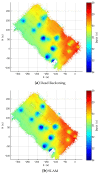
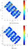
This paper describes a pose-based underwater 3D Simultaneous Localization and Mapping (SLAM) using a multibeam echosounder to produce high consistency underwater maps. The proposed algorithm compounds swath profiles of the seafloor with dead reckoning localization to build surface patches (i.e., point clouds). An Iterative Closest Point (ICP) with a probabilistic implementation is then used to register the point clouds, taking into account their uncertainties. The registration process is divided in two steps: (1) point-to-point association for coarse registration and (2) point-to-plane association for fine registration. The point clouds of the surfaces to be registered are sub-sampled in order to decrease both the computation time and also the potential of falling into local minima during the registration. In addition, a heuristic is used to decrease the complexity of the association step of the ICP from O(n2) to O(n) . The performance of the SLAM framework is tested using two real world datasets: First, a 2.5D bathymetric dataset obtained with the usual down-looking multibeam sonar configuration, and second, a full 3D underwater dataset acquired with a multibeam sonar mounted on a pan and tilt unit.
Keywords: 3D; AUV; SLAM; bathymetry; multibeam.
Figures





Similar articles
-
AUV SLAM method based on SO-CFAR and ADT feature extraction.Sci Prog. 2024 Oct-Dec;107(4):368504241286969. doi: 10.1177/00368504241286969. Sci Prog. 2024. PMID: 39360650 Free PMC article.
-
Underwater Localization and Mapping Based on Multi-Beam Forward Looking Sonar.Front Neurorobot. 2022 Jan 7;15:801956. doi: 10.3389/fnbot.2021.801956. eCollection 2021. Front Neurorobot. 2022. PMID: 35095458 Free PMC article.
-
Adjustment of Sonar and Laser Acquisition Data for Building the 3D Reference Model of a Canal Tunnel.Sensors (Basel). 2015 Dec 11;15(12):31180-204. doi: 10.3390/s151229855. Sensors (Basel). 2015. PMID: 26690444 Free PMC article.
-
Registration of Laser Scanning Point Clouds: A Review.Sensors (Basel). 2018 May 21;18(5):1641. doi: 10.3390/s18051641. Sensors (Basel). 2018. PMID: 29883397 Free PMC article. Review.
-
Direction-of-Arrival Estimation Methods in Interferometric Echo Sounding.Sensors (Basel). 2020 Jun 23;20(12):3556. doi: 10.3390/s20123556. Sensors (Basel). 2020. PMID: 32585964 Free PMC article. Review.
Cited by
-
An Improved Otsu Threshold Segmentation Method for Underwater Simultaneous Localization and Mapping-Based Navigation.Sensors (Basel). 2016 Jul 22;16(7):1148. doi: 10.3390/s16071148. Sensors (Basel). 2016. PMID: 27455279 Free PMC article.
-
H-SLAM: Rao-Blackwellized Particle Filter SLAM Using Hilbert Maps.Sensors (Basel). 2018 May 1;18(5):1386. doi: 10.3390/s18051386. Sensors (Basel). 2018. PMID: 29723975 Free PMC article.
-
Elevation Angle Estimations of Wide-Beam Acoustic Sonar Measurements for Autonomous Underwater Karst Exploration.Sensors (Basel). 2020 Jul 20;20(14):4028. doi: 10.3390/s20144028. Sensors (Basel). 2020. PMID: 32698493 Free PMC article.
-
3DupIC: An Underwater Scan Matching Method for Three-Dimensional Sonar Registration.Sensors (Basel). 2022 May 10;22(10):3631. doi: 10.3390/s22103631. Sensors (Basel). 2022. PMID: 35632037 Free PMC article.
-
Semantic Mapping for Autonomous Subsea Intervention.Sensors (Basel). 2021 Oct 11;21(20):6740. doi: 10.3390/s21206740. Sensors (Basel). 2021. PMID: 34695951 Free PMC article.
References
-
- Panish R., Taylor M. Achieving high navigation accuracy using inertial navigation systems in autonomous underwater vehicles; Proceedings of the MTS/IEEE Oceans; Santander, Spain. 6–9 June 2011; pp. 1–7.
-
- Kinsey J.C., Whitcomb L.L. Preliminary field experience with the DVLNAV integrated navigation system for oceanographic submersibles. Control Eng. Pract. 2004;12:1541–1549. doi: 10.1016/j.conengprac.2003.12.010. - DOI
-
- Batista P., Silvestre C., Oliveira P. Single Beacon Navigation: Observability Analysis and Filter Design; Proceedings of the American Control Conference (ACC); Baltimore, MD, USA. 30 June–2 Juny 2010; pp. 6191–6196.
-
- Vallicrosa G., Ridao P., Ribas D. AUV Single Beacon Range-Only SLAM with a SOG Filter. IFAC Workshop Navig. Guid. Control Underw. Veh. 2015;48:26–31. doi: 10.1016/j.ifacol.2015.06.005. - DOI
-
- Thomas H.G. GIB Buoys: An Interface Between Space and Depths of the Oceans; Proceedings of the Workshop on Autonomous Underwater Vehicles; Cambridge, MA, USA. 20–21 August 1998; pp. 181–184.
Publication types
LinkOut - more resources
Full Text Sources
Other Literature Sources

