Review
. 2020 May 24;25(10):2446.
doi: 10.3390/molecules25102446.

Polymers and Plastics Modified Electrodes for Biosensors: A Review

Affiliations
Review

Polymers and Plastics Modified Electrodes for Biosensors: A Review

Sonia Lanzalaco et al. Molecules. .

Abstract

Polymer materials offer several advantages as supports of biosensing platforms in terms of flexibility, weight, conformability, portability, cost, disposability and scope for integration. The present study reviews the field of electrochemical biosensors fabricated on modified plastics and polymers, focusing the attention, in the first part, on modified conducting polymers to improve sensitivity, selectivity, biocompatibility and mechanical properties, whereas the second part is dedicated to modified "environmentally friendly" polymers to improve the electrical properties. These ecofriendly polymers are divided into three main classes: bioplastics made from natural sources, biodegradable plastics made from traditional petrochemicals and eco/recycled plastics, which are made from recycled plastic materials rather than from raw petrochemicals. Finally, flexible and wearable lab-on-a-chip (LOC) biosensing devices, based on plastic supports, are also discussed. This review is timely due to the significant advances achieved over the last few years in the area of electrochemical biosensors based on modified polymers and aims to direct the readers to emerging trends in this field.

Keywords: conducting polymers; flexible electrochemical biosensors; modified bioplastics; modified biopolymers; recyclable plastics.


Conflict of interest statement

The authors declare no conflict of interest.

Figures

Figure 1
Figure 1
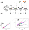
(a) Comparison between the evolution of electrochemical-based sensors published research papers per year in the last decade, based on polymer materials and employed in the biomedical field and (b) percentage of biosensors based on electrochemical detection composed made of unmodified and modified polymers. Source: Web of Science (WOS).
Figure 2
Figure 2
(a) TEM micrographs of poly(o-anisidine) (POA)-silver nanoparticles (AgNPs) hybrid (ratio 3:1); (b) differential pulse voltammograms of POA-AgNPs in 0.1-M PBS (pH 7.0) containing different concentrations of dopamine (DA) and nicotinamide adenine dinucleotide NADH (from inner to outer). Adapted with permission from reference [59]. Copyright © 2017 Elsevier B.V.
Figure 3
Figure 3
Cyclic voltammograms for the oxidation of (a) poly(N-methylpyrrole) (PNMPy)- and (b) PNMPy/ gold nanoparticles (AuNPs)-modified carbon electrodes (GCEs) in the absence and presence of different dopamine (DA) concentrations (from 1 to 10 mM). Scan rate: 100 mV/s; initial and final potential: −0.40 V; reversal potential: +0.80 V. For each graphic, labels a-e refer to DA concentrations of 0, 1, 3, 6 and 10 mM, respectively; (c) calibration curve for DA concentrations ranging from 1 to 100 μM (inset: from 1 to 10 μM) in 0.1-M PBS and (d) calibration curve for DA concentrations ranging from 1 to 100 μM in 0.1-M PBS with 200-μM ascorbic acid and 100-μM uric acid, acting as interferents at), poly(3,4-ethylenedioxythiophene) (PEDOT)/PNMPy/PEDOT (3l-5s) and PEDOT/PNMPy/PEDOT/AuNPs (3l-5s/AuNP-4) electrodes. (a,b) Adapted with permission from reference [68], Copyright © 2011 American Chemical Society and (c,d) from reference [69], Copyright © 2014 American Chemical Society.
Figure 4
Figure 4
Reaction procedure for the preparation of polypyrrole nanotubes (PPyNTs)/poly(ionic liquids) (PILs)/gold nanoparticles (AuNPs). High-density and well-dispersed AuNPs could be deposited on the surface of PPyNTs/PILs by anion-exchange of PILs with Au precursor and the in situ reduction of the metal ions, due to the presence of PILs. Reprinted with permission from reference [70]. Copyright © 2017 Elsevier B.V.
Figure 5
Figure 5
(a) Schematic route for the preparation of the integrated paper-based analytical device; (b) differential pulse voltammetry (DPV) response of the saliva sample using 5 disposable electrodes fabricated independently and (c) electrochemical response of saliva samples spiked with increasing concentrations of uric acid in 200 mM increments (inset calibration plot). Adapted with permission from reference [83]. Copyright © 2019 Elsevier B.V.
Figure 6
Figure 6
Chemical route for the preparation of molecularly imprinted polymer (MIP) polypyrrole (PPy)/ carbon nanotubes (CNTs). Reprinted with permission from reference [87]. Copyright © 2014 Elsevier B.V.
Figure 7
Figure 7
(a) Schematic representation of the PAni-AuNPs/DNA construction and (b) cyclic voltammograms or the biosensor exposed to different concentrations of recombinant plasmid containing the BCR/ABL fusion gene breakpoint cluster region- Abelson tyrosine kinase gene (DNA _target: 0.0694, 0.694, 6.94, 69.4, 694 fM) and nonspecific plasmid (negative control). Adapted with permission from reference [38]. Copyright © 2016 Elsevier B.V.
Figure 8
Figure 8
TEM micrograph of polythiophene (PTh)-g-(poly(ethylene glycol) (PEG)-r-biopolymer polycaprolactone (PCL) at (a) low magnification and (b) high magnifications. Porous spherical particles were highlighted with red circles while, rod-like structures are marked with rectangular forms and yellow arrows. Reprinted with permission from reference [96]. Copyright © The Royal Society of Chemistry 2019.
Figure 9
Figure 9
(a) Schematic illustration of of α-fetoprotein (AFP) biosensor synthesis; (b) impedance spectra corresponding to the biosensor with different antigen concentrations (0.01-M PBS, pH 7.4), curves from inner to outer represent 10 fg/mL, 1 fg/mL, 10−1 fg/mL, 10−2 fg/mL, 10−3 fg/mL AFP antigen, respectively; (c) responses of the AFP biosensor to bovine serum albumin (BSA) (1.0 nM), human serum albumin (HSA) (1.0 nM), hemoglobin (HGB) (1.0 nM), DNA sequence (1.0 nM), AFP antigen (1.0 fg/mL) and a mixture of all the above substances, respectively. Adapted with permission from reference [41]. Copyright © 2016 Elsevier B.V.
Figure 10
Figure 10
(a) Effect of vitamin B12 concentration on reduction peak currents of Co(II) to Co(I) using (A) single walled carbon nanotube (SWCNT)–chitosan modified PGE, (B) chitosan modified PGE at pH 2.0; (b) The effect of vitamin B12 concentration on reduction peak currents of Co(II) to Co(I) using (A) SWCNT–chitosan modified PGE; (B) chitosan modified PGE at pH 5.0. Adapted with permission from reference [108]. Copyright © 2011 Elsevier B.V.
Figure 11
Figure 11
Schematic diagram of the preparation procedure of the molecular imprinted electrochemical sensor. Adapted with permission from reference [43]. Copyright © 2015 Elsevier.
Figure 12
Figure 12
(a) Calibration curve of the prepared (A) molecularly imprinted (MIPs)/chitosan (CS)/ionic liquid–graphene (IL-GR) modified glassy carbon electrode (GCE) (MIPs/CS/IL–GR/GCE) and (B) MIPs/CS/IL–GR/GCE for different concentrations of BSA in PBS containing 0.10-mM [Fe(CN)6] 3−/4− (pH 7.0) (insert: the DPVs with different concentrations of bovine serum albumin (BSA) on MIPs/CS/IL–GR/GCE); (b) selectivity of MIPs/CS/IL–GR/GCE and MIPs/CS/IL–GR/GCE for BSA, human serum albumin (HSA) and bovine hemoglobin (BHb). The concentration of each protein is 1.0 × 10⁻⁶ g/L. Reprinted with permission from reference [43]. Copyright © 2015 Elsevier B.V.
Figure 13
Figure 13
Clozapine (CLZ) as an oxidizing mediator in the catechol-modified chitosan system. (a) Schematic of the system with the diffusing CLZ; (b) continuous oxidation of CLZ in the presence of catechol (Q) reduction; (c) CLZ acts as an oxidizing mediator of QH2 and Ru2+ as a reducing mediator regenerating the Q. Electrochemical potential bar represents standard reduction potential of Ru2+, Q and CLZ. Reprinted with permission from reference [44]. Copyright © 2015 © 2014 Elsevier, Ltd.
Figure 14
Figure 14
(a) Representation of the 3D-printed graphene/PLA electrodes’ fabrication, digestion/activation and application: first, coin-shaped electrodes from the graphene/PLA composite filament are 3D-printed with a fused deposition modeling printer. After proteinase K-mediated PLA digestion, the electrodes’ surface becomes eroded and electroactive. The resulting activated surface is used to immobilize alkaline phosphatase (ALP) enzyme via adsorption. ALP catalyzes the conversion of 1-naphthyl phosphate into 1-naphthol, which is electrochemically oxidized at the surface of 3D-printed electrodes. Electrooxidation of 1-naphthol at the digested 3D-printed sur- faces; (b) CVs performed on the activated 3D-printed electrodes and glassy carbon electrode (GCE) in the presence of 1-naphthol (60 μM); (c) progression of maximum current density ( jp) and peak potential (Ep) with the number of scans, on activated 3D-printed surfaces. Reprinted with permission from reference [46]. Copyright © The Royal Society of Chemistry 2019.
Figure 15
Figure 15
Schematic representation of synthesis and detection of vitamin C using graphene-iron oxide-polyvinyl alcohol (PIG). Reprinted with permission from reference [47]. Copyright © 2018 Elsevier B.V.
Figure 16
Figure 16
SEM micrographs of (a) poly(3,4-ethylenedioxythiophene) (PEDOT) and (b) poly(N-cyanoethylpyrrole) (PNCPy) before (left) and after (right) plasma treatment using tcp = 2 min. (c) DA detection limit of PEDOT- and PNCPy-modified glassy carbon electrodes (GCEs) with cold- plasma treatment, as obtained from the standard addition of 10 μL of DA to 10 mL of 0.1-M PBS. Anodic peak intensity (ip) was determined by CV using a scan rate of 50 mV s−1; (d) control voltammograms of 100 μ-M DA in 0.1-M PBS at cold-plasma treated PEDOT-modified GCE prepared using different tcp values. Scan rate: 100 mV/s. Reprinted with permission from reference [48]. Copyright © 2016 Elsevier B.V.
Figure 17
Figure 17
(a) Current–time plots for the untreated low-density polyethylene (U-LDPE)/glucose oxidase (GOx) and treated low-density polyethylene (PT- LDPE)/GOx (tcp = 30 s, 1 and 2 min) upon the successive addition in 0.1-M PBS of 1 mM glucose; (b) current–density response versus glucose concentration for the three sensors mentioned above. Error bars indicate standard deviations for five measurements using independent electrodes. The calibration curve equation is also displayed. Current–time plots for the PT-LDPE/GOx sensors (tcp = 1 and 2 min in red and blue, respectively) upon the successive addition in 0.1-M PBS of: (c) 1 mM glucose, 1 mM uric acid (UA), 1 mM ascorbic acid (AA) and 1 mM dopamine (DA); (d) 1 mM glucose, 0.1 mM UA, 0.1 mM AA and 0.1 mM DA. Polarization potential: 0.50 V versus Ag|AgCl. Reprinted with permission from reference [49]. Copyright © 2017 WILEY-VCH Verlag GmbH & Co. KGaA, Weinheim.
Figure 18
Figure 18
(1) Bio-polyethylene terephthalate (PET) pretreatment; (2) photoresist deposition on substrate; (3) exposure to ultraviolet radiation for electrode delimitation; (4) removal of the sensitized photoresist with the developer solution, followed by washing and drying; (5) patterned substrate treatment with O2 plasma; (6) substrate treatment with O2 plasma; (7) removal of excess coating and washing material; (8) individually cut flexible platinum electrodes. Reprinted with permission from reference [50]. Copyright © 2020 Elsevier B.V.
Figure 19
Figure 19
(a) Preparation scheme of the biosensor showing the steps of construction of the self-assembled monolayer, immobilization of the antibody and immunocomplex formation; (b) scheme showing increased resistance to electron transfer as further modifications are made on the working electrode surface; (c,d) Nyquist diagrams of (●) platinum electrode (Pt), () Pt-cysteamine, () Pt-cysteamine-glutaraldehyde, () Pt-cysteamine-glutaraldehyde-antibody and () Pt-cysteamine-glutaraldehyde-antibody-PARK7/DJ-1 protein; (e) equivalent circuit used for simulation of the experimental data, in the presence of redox couples. Reprinted with permission from reference [50]. Copyright © 2020 Elsevier B.V.
Figure 20
Figure 20
Fabrication and function of the Chem–Phys hybrid sensor patch. (a) Schematic showing the screen-printing process; (b) image of the Chem–Phys printing stencil; (c) An array of printed Chem–Phys flexible patches; (d) image of a Chem–Phys patch along with the wireless electronics; (e) Schematic showing the LOx-based lactate biosensor along with the enzymatic and detection reactions; (f) block diagram of the wireless readout circuit. Reprinted with permission from reference [144]. Copyright © Springer Nature Limited.
Figure 21
Figure 21
(a) Photograph of the mouthguard biosensor integrated with wireless amperometric circuit board; (b) reagent layer of the chemically modified printed Prussian blue carbon working electrode containing uricase for salivary uric acid (SUA) biosensor; (c) photograph of the wireless amperometric circuit board: front side (left) and back side (right). Reprinted with permission from reference [148]. Copyright © 2015 Elsevier B.V.
Figure 22
Figure 22
l-lactate sensor on contact lens. (a) Schematic of the fabrication process for sensors on the transparent polyethylene terephthalate (PET) substrate, which is molded into a contact lens shape; (b) flat substrate with sensing structure, interconnects and electrode pads for connection to the external potentiostat; (c) completed contact lens sensor held on a finger. Reprinted with permission from reference [150]. Copyright © 2011 Elsevier B.V.

Similar articles

Cited by

References

    1. Arduini F., Cinti S., Scognamiglio V., Moscone D., Palleschi G. How cutting-edge technologies impact the design of electrochemical (bio)sensors for environmental analysis. A review. Anal. Chim. Acta. 2017;959:15–42. doi: 10.1016/j.aca.2016.12.035. - DOI - PubMed
    1. Yang Y., Yang X., Tan Y., Yuan Q. Recent progress in flexible and wearable bio-electronics based on nanomaterials. Nano Res. 2017;10:1560–1583. doi: 10.1007/s12274-017-1476-8. - DOI
    1. Soper S.A., Brown K., Ellington A., Frazier B., Garcia-manero G., Gau V., Gutman S.I., Hayes D.F., Korte B., Landers J.L., et al. Point-of-care biosensor systems for cancer diagnostics/prognostics. Biosens. Bioelectron. 2006;21:1932–1942. doi: 10.1016/j.bios.2006.01.006. - DOI - PubMed
    1. Bruen D., Delaney C., Florea L., Diamond D. Glucose Sensing for Diabetes Monitoring: Recent Developments. Sensors. 2017;17:1866. doi: 10.3390/s17081866. - DOI - PMC - PubMed
    1. Cui F., Zhou Z., Zhou H.S. Molecularly Imprinted Polymers and Surface Imprinted Polymers Based Electrochemical Biosensor for Infectious Diseases. Sensors. 2020;20:996. doi: 10.3390/s20040996. - DOI - PMC - PubMed

LinkOut - more resources

  NODES
twitter 2