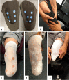
A personalised prosthetic liner with embedded sensor technology: a case study
- PMID: 32928238
- PMCID: PMC7491094
- DOI: 10.1186/s12938-020-00814-y
A personalised prosthetic liner with embedded sensor technology: a case study
Erratum in
-
Correction: A personalised prosthetic liner with embedded sensor technology: a case study.Biomed Eng Online. 2023 Sep 21;22(1):93. doi: 10.1186/s12938-023-01154-3. Biomed Eng Online. 2023. PMID: 37735429 Free PMC article. No abstract available.
Abstract
Background: Numerous sensing techniques have been investigated in an effort to monitor the main parameters influencing the residual limb/prosthesis interface, fundamental to the optimum design of prosthetic socket solutions. Sensing integration within sockets is notoriously complex and can cause user discomfort. A personalised prosthetic liner with embedded sensors could offer a solution. However, to allow for a functional and comfortable instrumented liner, highly customised designs are needed. The aim of this paper is to presents a novel approach to manufacture fully personalised liners using scanned three-dimensional image data of the patient's residual limb, combined with designs that allow for sensor integration. To demonstrate the feasibility of the proposed approach, a personalised liner with embedded temperature and humidity sensors was realised and tested on a transtibial amputee, presented here as a case study.
Methods: The residual limb of a below knee amputee was first scanned and a three-dimensional digital image created. The output was used to produce a personalised prosthesis. The liner was manufactured using a cryogenic Computer Numeric Control (CNC) machining approach. This method enables fast, direct and precise manufacture of soft elastomer products. Twelve Hygrochron Data Loggers, able to measure both temperature and humidity, were embedded in specific liner locations, ensuring direct sensor-skin contact. The sensor locations were machined directly into the liner, during the manufacturing process. The sensors outputs were assessed on the below amputee who took part in the study, during resting (50 min) and walking activities (30 min). To better describe the relative thermal properties of new liner, the same tests were repeated with the amputee wearing his existing liner. Quantitative comparisons of the thermal properties of the new liner solution with that currently used in clinical practice are, therefore, reported.
Results: The liner machining process took approximately 4 h. Fifteen minutes after donning the prosthesis, the skin temperature reached a plateau. Physical activity rapidly increased residuum skin temperatures, while cessation of activity caused a moderate decrease. Humidity increased throughout the observation period. In addition, the new liner showed better thermal properties with respect to the current liner solution (4% reduction in skin temperature).
Conclusions: This work describes a personalised liner solution, with embedded temperature and humidity sensors, developed through an innovative approach. This new method allows for a range of sensors to be smoothly embedded into a liner, which is capable of measuring changes in intra-socket microclimate conditions, resulting in the design of advanced socket solutions personalised specifically for individual requirements. In future, this method will not only provide a personalised liner but will also enable dynamic assessment of how a residual limb behaves within the socket during daily activities.
Keywords: Cryogenic CNC machining; Humidity; Lower limb; Prosthetic liner; Prosthetic socket; Temperature; Transtibial amputation.
Conflict of interest statement
The authors declare that they have no competing interests.
Figures


Similar articles
-
Quantifying Bone and Skin Movement in the Residual Limb-Socket Interface of Individuals With Transtibial Limb Loss Using Dynamic Stereo X-Ray: Protocol for a Lower Limb Loss Cadaver and Clinical Study.JMIR Res Protoc. 2024 Apr 26;13:e57329. doi: 10.2196/57329. JMIR Res Protoc. 2024. PMID: 38669065 Free PMC article.
-
Skin Temperature Prediction in Lower Limb Prostheses.IEEE J Biomed Health Inform. 2016 Jan;20(1):158-65. doi: 10.1109/JBHI.2014.2368774. Epub 2014 Nov 7. IEEE J Biomed Health Inform. 2016. PMID: 25389248
-
Additive manufacturing techniques for smart prosthetic liners.Med Eng Phys. 2021 Jan;87:45-55. doi: 10.1016/j.medengphy.2020.11.006. Epub 2020 Nov 13. Med Eng Phys. 2021. PMID: 33461673
-
Sensing and actuation technologies for smart socket prostheses.Biomed Eng Lett. 2019 Nov 12;10(1):103-118. doi: 10.1007/s13534-019-00137-5. eCollection 2020 Feb. Biomed Eng Lett. 2019. PMID: 32175132 Free PMC article. Review.
-
Techniques for Interface Stress Measurements within Prosthetic Sockets of Transtibial Amputees: A Review of the Past 50 Years of Research.Sensors (Basel). 2016 Jul 20;16(7):1119. doi: 10.3390/s16071119. Sensors (Basel). 2016. PMID: 27447646 Free PMC article. Review.
Cited by
-
Quantitative analysis of interface pressures in transfemoral prosthetic sockets.Prosthet Orthot Int. 2024 Apr 1;48(2):176-183. doi: 10.1097/PXR.0000000000000251. Epub 2023 Jun 28. Prosthet Orthot Int. 2024. PMID: 37379468 Free PMC article.
-
Assessment of Low-Density Force Myography Armband for Classification of Upper Limb Gestures.Sensors (Basel). 2023 Mar 1;23(5):2716. doi: 10.3390/s23052716. Sensors (Basel). 2023. PMID: 36904919 Free PMC article.
-
A Sensor-Based Decision Support System for Transfemoral Socket Rectification.Sensors (Basel). 2021 May 28;21(11):3743. doi: 10.3390/s21113743. Sensors (Basel). 2021. PMID: 34071273 Free PMC article.
-
A clinical comparison of a digital versus conventional design methodology for transtibial prosthetic interfaces.Sci Rep. 2024 Oct 28;14(1):25833. doi: 10.1038/s41598-024-74504-3. Sci Rep. 2024. PMID: 39468101 Free PMC article.
-
Soft robotics in wearable and implantable medical applications: Translational challenges and future outlooks.Front Robot AI. 2023 Feb 8;10:1075634. doi: 10.3389/frobt.2023.1075634. eCollection 2023. Front Robot AI. 2023. PMID: 36845334 Free PMC article.
References
-
- Mak AF, Zhang M, Boone DA. State-of-the-art research in lower-limb prosthetic biomechanics-socket interface: a review. JRRD. 2001;38(2):161–174. - PubMed
-
- Kapp S, Miller JA “Chapter 20 Lower Limb Prosthetic.”
-
- He Q, Johnston J, Zeitlinger J, City K, City K. HHS Public Access”. PLos ONE. 2015;33(4):395–401. - PubMed
MeSH terms
LinkOut - more resources
Full Text Sources

