A Novel Size-Based Centrifugal Microfluidic Design to Enrich and Magnetically Isolate Circulating Tumor Cells from Blood Cells through Biocompatible Magnetite-Arginine Nanoparticles
- PMID: 39338775
- PMCID: PMC11436177
- DOI: 10.3390/s24186031
A Novel Size-Based Centrifugal Microfluidic Design to Enrich and Magnetically Isolate Circulating Tumor Cells from Blood Cells through Biocompatible Magnetite-Arginine Nanoparticles
Abstract
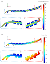
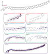
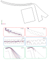
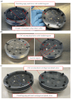
This paper presents a novel centrifugal microfluidic approach (so-called lab-on-a-CD) for magnetic circulating tumor cell (CTC) separation from the other healthy cells according to their physical and acquired chemical properties. This study enhances the efficiency of CTC isolation, crucial for cancer diagnosis, prognosis, and therapy. CTCs are cells that break away from primary tumors and travel through the bloodstream; however, isolating CTCs from blood cells is difficult due to their low numbers and diverse characteristics. The proposed microfluidic device consists of two sections: a passive section that uses inertial force and bifurcation law to sort CTCs into different streamlines based on size and shape and an active section that uses magnetic forces along with Dean drag, inertial, and centrifugal forces to capture magnetized CTCs at the downstream of the microchannel. The authors designed, simulated, fabricated, and tested the device with cultured cancer cells and human cells. We also proposed a cost-effective method to mitigate the surface roughness and smooth surfaces created by micromachines and a unique pulsatile technique for flow control to improve separation efficiency. The possibility of a device with fewer layers to improve the leaks and alignment concerns was also demonstrated. The fabricated device could quickly handle a large volume of samples and achieve a high separation efficiency (93%) of CTCs at an optimal angular velocity. The paper shows the feasibility and potential of the proposed centrifugal microfluidic approach to satisfy the pumping, cell sorting, and separating functions for CTC separation.
Keywords: Dean drag force; biocompatible magnetite–arginine nanoparticles; centrifugal microfluidics; inertial microfluidics; magnetic circulating tumor cell separation; microfabrication.
Conflict of interest statement
The authors declare that they have no conflicts of interest.
Figures


Similar articles
-
An experimental study of centrifugal microfluidic platforms for magnetic-inertial separation of circulating tumor cells using contraction-expansion and zigzag arrays.J Chromatogr A. 2023 Sep 13;1706:464249. doi: 10.1016/j.chroma.2023.464249. Epub 2023 Jul 29. J Chromatogr A. 2023. PMID: 37531849
-
Design of a novel integrated microfluidic chip for continuous separation of circulating tumor cells from peripheral blood cells.Sci Rep. 2022 Oct 11;12(1):17016. doi: 10.1038/s41598-022-20886-1. Sci Rep. 2022. PMID: 36220844 Free PMC article.
-
Recent Developments in Inertial and Centrifugal Microfluidic Systems along with the Involved Forces for Cancer Cell Separation: A Review.Sensors (Basel). 2023 Jun 2;23(11):5300. doi: 10.3390/s23115300. Sensors (Basel). 2023. PMID: 37300027 Free PMC article. Review.
-
Design and Application of Microfluidic Capture Device for Physical-Magnetic Isolation of MCF-7 Circulating Tumor Cells.Biosensors (Basel). 2024 Jun 15;14(6):308. doi: 10.3390/bios14060308. Biosensors (Basel). 2024. PMID: 38920612 Free PMC article.
-
[Recent advances in isolation and detection of circulating tumor cells with a microfluidic system].Se Pu. 2022 Mar 8;40(3):213-223. doi: 10.3724/SP.J.1123.2021.07009. Se Pu. 2022. PMID: 35243831 Free PMC article. Review. Chinese.
References
-
- Liu H.Y., Hille C., Haller A., Kumar R., Pantel K., Hirtz M. Highly efficient capture of circulating tumor cells by microarray in a microfluidic device. FASEB J. 2019;33:lb230. doi: 10.1096/fasebj.2019.33.1_supplement.lb230. - DOI
-
- Kim M.S., Moon H.S., Kim S.S., Park J.M., Huh N. A novel fully automated centrifugal microfluidic platform with massive volume capability to isolate circulating tumor cells; Proceedings of the 17th International Conference on Miniaturized Systems for Chemistry and Life Sciences, MicroTAS 2013; Freiburg, Germany. 27–31 October 2013; San Diego, CA, USA: Chemical and Biological Microsystems Society; 2013. pp. 958–960.
-
- Farahinia A., Zhang W., Badea I. Novel microfluidic approaches to circulating tumor cell separation and sorting of blood cells: A review. J. Sci. Adv. Mater. Devices. 2021;6:303–320. doi: 10.1016/j.jsamd.2021.03.005. - DOI
MeSH terms
Substances
Grants and funding
LinkOut - more resources
Full Text Sources
Miscellaneous

